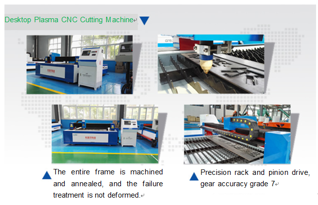
The CNC Plasma Cutting Machine is equipped with a cutting tool that cuts the object. This mechatronic Cutting Machine is called a Cnc Cutting Machine. Most cutting machine systems can be cut by combining with CAD graphics. In the CNC cutting machine, the relative coordinates and absolute coordinates are also divided. Today, we will analyze the relative and absolute coordinates of the CNC cutting mechanism diagram. It is worth mentioning that mechanical drawing is very important. It can display various parts in a comprehensive and comprehensive manner. For Cnc Plasma Cutting Machine, the mathematical processing of numerical control part drawing is mainly to calculate the size of the part processing track, that is, calculate the part. The base point of the contour and the coordinates of the node, or the base point of the tool center contour and the coordinates of the node, to program the machining program. When driving a precision CNC Plasma Cutting Machine with a digital program, the relevant requirements for the positioning control system are as follows:
I. Introduction of the relative coordinate system of precision CNC plasma cutting machine
1. Relative Cartesian coordinates: @dx, dy; coordinate increments to the previous point; 2. Relative polar coordinates: @distance
II. The precision CNC plasma cutting machine absolute coordinate system
1. Cartesian coordinates (x, y, z) The x coordinate represents the position in the horizontal direction, and the y coordinate represents the position in the vertical direction. The coordinates of any point in the 2D map can be located in the form of (x, y). 2. Polar coordinates: distance < angle. You can enter the distance of a point from the origin and its angle in the xy plane to determine the point. For example, 10<45 indicates a point at which the distance from the origin is 10 and the angle with respect to the x-axis is 45 degrees.
III. Precision CNC plasma cutting machine base point coordinate algorithm
Generally, CNC plasma cutting machines have only linear and circular interpolation functions. For a plane profile consisting of a straight line and an arc, the main task of numerical calculation during programming is to find the coordinates of each base point.

Here we call the base point, which means that the intersection or tangent point of the different geometrical lines that make up the contour of the part is called the base point. The base point can be directly used as the starting point or end point of its motion trajectory.
The coordinate calculation of the precision CNC plasma cutting machine needs to be based on the requirements of filling in the processing program list. The direct calculation of the base point includes: the coordinates of the starting point and the end point of each motion track in the selected coordinate system, and the circular motion track. Center coordinate value.
The method of direct calculation of the base point of the precision CNC plasma cutting machine is relatively simple, and can generally be done manually according to the known conditions given by the part pattern. That is, the values are directly calculated based on the knowledge of algebra, triangle, geometry, or analytic geometry given by the given dimensions on the part pattern. When calculating, be careful to keep enough digits after the decimal point to ensure sufficient accuracy.
IV. Precision CNC plasma cutting machine node coordinate positioning
For some planar contours, the non-circular equation curve Y=F(X) composition, such as involute, Archimedes spiral, etc., can only be approximated by straight lines and arcs that can be processed. The task of numerical calculation at this time is to calculate the coordinates of the node.
When using a CNC machine tool that does not have non-circular curve interpolation function to machine parts with non-circular curve contours, in the preparation of the machining program, multiple straight line segments or arcs are often used to approximate the non-circular curve. This is called fitting. deal with. The intersection or tangent of a fitted line segment is called a node.
The computational node coordinates of the node coordinates are difficult to calculate and the workload is large, so it is often completed by a computer, and can also be manually calculated if necessary. Commonly used linear approximation methods (equal spacing method, equal step method, and equal error method) Arc approach method.
Because of the advanced nature, complexity and rapid development of precision CNC plasma cutting machines, as well as the variety of models and grades, and the price is relatively expensive, when using precision CNC plasma cutting machine, it should be Leading and professional technicians conduct in-depth and meticulous research, or entrust a consulting agency composed of experienced CNC experts to consult or represent, so as to correctly select precision CNC plasma cutting machine equipment.
